PDF Brochure Concrete Porous Pipes
MS 525 - 1986
BS 1194 - 1969
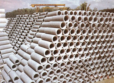
High Frequency Vibrated  | OKA Concrete Porous Pipes are manufactured in accordance with BS 1194 -1969 and MS 525 -1986.
They are manufactured by a combination of high frequency vibration and extrusion method which produces a strong pipe of high and consistent quality and are extensively used for sub-soil drainage to meet a variety of needs.
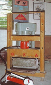
| | OKA Concrete Porous Pipe Under loading Test. |  |
General
The use of 'OKA' Concrete Porous Pipe is undoubtedly a great advantage both in efficiency and economy. Its strength is much greater than the ordinary clay subsoil pipe, and INCREASES WITH AGE, as it remain unaffected by the absorption of moisture or by the variations in climatic conditions.
The saving in trenching, and the rapidity of laying more than compensate for higher cost of the pipes, and when the certainty of correct operations at little or no extra cost for maintenance is taken into account, the superiority of Porous Concrete Pipes for Land Drainage is uncontestable.
The unique property of Porous Concrete Pipes is that infiltration of water takes place over the entire surface so that, in fact , the pipe-line enjoys the best characteristics of the rubble drain with the additional advantage of a central duct for the rapid removal of water. The porosity is so remarkable that small drains may be connected to larger ones merely by placing the end of the former over the latter without the need for piercing the wall of the main to enable it to receive the flow from the subsidiary. Description 'OKA' Porous Concrete Pipe are produced from the finest quality materials on up-to date equipment. They are uniform in length and diameter and are highly porous. They have rebated joints and are available in 450mm (1' 6") lengths, from 100mm (4") to 300mm (12") internal diameter. 'OKA' Pipes are thoroughly matured before delivery, thus minimising the risk of breakage in transit or on site. Application 'OKA' Porous Pipe are being used in ever-increasing numbers under road-verges for subsoil drainage and the removal of surplus water; they are also being widely used for this purpose on railways, where flooding of the track would be a very serious matter Their extensive use for aerodrome drainage is interesting for many reasons. In the first place, they process adequate strength to withstand impact loads from aircraft; they may be widely spaced, thus showing savings in cost and a mininum surface disturbance; and as the continuous infiltration principle banishes the possibility of subsidence, the risk of dangerous depression in the surface of the aerodrome over the drainage system is absent. 'OKA' Porous Pipe are used extensively on highways, Aerodromes, Golf Courses, Housing Sites, Recreation Ground, Race Tracks, Tennis Courts, Football Fields etc. They ensure rapid removal of all surplus water, yet by capillary attraction, retain sufficient moisture in the soil to promote a healthy condition of the turf. All pipes shall be laid in a trench and backfilled by approved filter material. For under road crossings or where ordered by the Engineer, the filter material shall be replaced by 'no-fines concrete'. | Grading for filter material | | Aggregate grading for 'no-fines concrete' | | BS Sieve Size | % by wt. passing | | BS Sieve Size | % by wt. passing | | (1 ½) 37.5 mm | 100 | | (3 ½) 90 mm | 100 | | (⅜) 10 mm | 45 -- 100 | | (1 ½) 37.5 mm | 85 -- 100 | | (7) 3.35 mm | 25 -- 80 | | (¾) 20 mm | 0 -- 20 | | (25) 0.500 mm | 8 -- 45 | | (⅜) 10 mm | 0 -- 5 | | (200) 0.075 mm | 0 -- 50 | | | |
ADVANTAGES
The advantages of 'OKA' Concrete Porous Pipe Ditches.
| a) | Considerable saving in land. | | b) | Little or no yearly maintenance.
(The initial cost of 'OKA' Porous Pipes can be offset against the normal yearly open ditch cleaning and maintenance costs.) | | c) | Several small fields can be joined into one, allowing larger machines to be used with subsequent economy. | | d) | The dangers of live stock falling into ditches is entirely eliminated. | | e) | The 'pipe ditch' can be located just exactly where it is required, as 'OKA' pipes are strong enough to withstand heavy loads. | | f) | Prevent necessity of close pipe line. | | g) | Rebate joints prevents the intrusion of roots, silt, etc as a special 'mix' is used to form an efficient joint at each end of the pipe to ensure alignment. | | h) | Function efficiently and permanently and required no maintenance provided pipes of sufficient capacity selected. |
REFERENCE TABLE
Nominal Internal Diameter
mm (in) | Effective Length
mm (in)
| Wall Thickness
mm (in) | Weight Per Pipe
Kg (lb)
| Rate of Infiltration
Lit / min / m (gal/ min/ ft)
See (a) and (b)
BS. 1194 - 1969
| 100 ( 4 )
150 ( 6 )
225 ( 9 )
300 ( 12 ) | 450 ( 18 )
450 ( 18 )
450 ( 18 )
450 ( 18 ) | 22 ( ⅞ )
25 ( 1 )
38 ( 1½ )
48 ( 1 ⅞ ) | 8 ( 17 )
12 ( 27 )
28 ( 62 )
42 ( 92 ) | 52 ( 3 ½ )
105 ( 7 )
158 ( 10 ½ )
263 ( 17 ½ )
|
| (a) | B.S. 1194 - 1969 Porosity Test states that each selected pipe shall have a rate of infliltration under a constant head of water two inches above the top of the pipe, of NOT LESS than as stated. | | (b) | The rate of infiltration for porous pipes with non-porous inverts shall not be less than one-half the figures given above porous pipes. |
NOTE :- - Extra Strength Pipes are made to order.
- All pipes available in ordinary portland cement.
- Special pipes using sulphate resisting cement, high alumina cement or other types of cement are made to order.
USEFULL DATA
RELATION BETWEEN DEPTH AND EFFECTIVE DRAINAGE AREA DRAIN INTERVALS | Depth | Open Soils | Medium Soils | Clay Soils | 1800mm ( 6 ft ) | 18m - 22m | 15m - 18m | 7m - 11m | | | ( 20 - 24 yds ) | ( 16 - 20 yds ) | ( 8 - 12 yds ) | 1500mm ( 5 ft ) | 16m - 18m | 12m - 16m | 6m - 9m | | | ( 17 - 20 yds ) | ( 13 - 17 yds ) | ( 7 - 10 yds ) | 1200mm ( 4 ft ) | 12m - 15m | 10m - 12m | 4.5m - 7m | | | ( 13 - 16 yds ) | ( 11 - 13 yds ) | ( 5 - 8 yds ) | 900mm ( 3 ft ) | 9m - 11m | 7m - 9m | 4m - 5.5 m | | | ( 10 - 12 yds ) | ( 8 - 10 yds ) | ( 4 - 6 yds ) | 600mm ( 2 ft ) | 6m - 7m | 4.5m - 6m | 2.7m - 4m | | | ( 7 - 8 yds ) | ( 5 - 7 yds ) | ( 3 - 4 yds ) | 450mm (1 ½ ft ) | 4.5m - 5.5m | 4 - 4.5m | 1.8m - 2.7m | | | ( 5 - 6 yds ) | ( 4 - 5 yds ) | ( 2 - 3 yds ) |
The above table is arrived at by applying the rule which states :-
A drain will affect the soil on either side of it to a distant equal in open soils to 5 to 6 times in depth, in medium soils 4 to 5 times, in clay soils 2 to 3 times. PIPE CAPACITIES | Diameter of Pipes | | Various Falls | | | mm (in) | 1/500 | 1/300 | 1/200 | 1/100 | 1/50 | | 100 (4) | 1,700 | 2,200 | 2,700 | 3,900 | 5,400 | | 150 (6) | 5,400 | 6,900 | 8,500 | 12,000 | 17,000 | | 225 (9) | 16,500 | 21,400 | 26,000 | 37,000 | 52,500 | | 300 (12) | 31,400 | 38,000 | 49,500 | 69,300 | 99,000 |
The above table gives the maximum rate of free flow in gallons per hours from pipes of from 100mm (4 ins) to 300mm (12 ins) internal diameter in the various falls. | | | LENGTH OF CHANNELS AND NUMBER OF PIPES REQUIRED TO DRAIN ONE ACRE | | Intervals | | | | | m | yds | | | | | 2.7 | (3) | ……………………… | 1475 m | ( 4,840 feet or 73.3 chains) | | 7 | (8) | ……………………… | 553 m | ( 1,815 feet or 27.5 chains) | | 10 | (11) | ……………………… | 402 m | (1,320 feet or 20.0 chains) | | 15 | (16) | ……………………… | 276 m | ( 907 feet or 13.8 chains) | | 20 | (22) | ……………………… | 201 m | ( 660 feet or 10.0 chains) |
1 inch of rain of 1 acre = 22,635 gallons or 101.1 tons.
1 inch = 943 gallons per acre per hour.
10 pounds of water = 1 gallon
1 cubic foot = 6.24 gallons
Go to Top Download PDF Brochure
|


